Jun 20


Field Day 2017 is nigh upon us! June 24-25th. We will be operating for the full 24 hours, 1300 hours Saturday thru 1300 hours on Sunday. Members will be arriving earlier, around 0930 hours, to do some permitted preliminary setup and arrange for logistics.

All SARC members are encouraged to participate in Field Day. Yes, you can bring all of your own equipment, but you don’t have to bring all of your equipment or even any equipment.

We welcome visitors of any type. It doesn’t matter if you aren’t a club member or a non ham operator. Everybody is welcomed.

Our location will be at Shavano Park’s City Hall, outside in the parking lot.   The address is 900 SaddleTree Ct, Shavano Park, just off of NW Military Drive, north of De Zavala Rd, and inside Loop 1604.

Read the rest of this entry »

Share
Oct 6

Pondering Thoughts

Revisiting a old published article!  Just because it is still relevant!

A recent conversation/situation made me think about some things. In my day job as a Diesel Truck/Heavy Equipment Technician, I drive a Dodge 3/4 ton truck with a service/tool bed on it. There are 3 compartments on each side with various shelving and such.

My tools are compartmentalized for the most part, with the tools I use the most in the center drivers side, mostly for lighter duty work of various complexities.  The front box on the drivers side are my heavier duty sockets, rackets, and wrenches. Also my various sprays and cleaners.  The rear drivers side box are pry bars, breaker bars, hammers, and large crescent and pipe wrenches.  In the boxes on the other side are separated by air tools, electrical and diagnostic tools, oils, air hoses, and of course one that is packed with various items left over and pack ratted for odd reasons that come in really handy sometimes.

Anyway, one evening on the way home, had to make a pit stop at Home Depot, so I locked the compartments in case someone decided they needed my tools worse than I did.

The next morning, the boss called kind of early. We had a regular customers truck broke down on I-10 and I had to get there quick to replace some air lines. Out the door I dash, without conducting my usual key, phone & wallet check before leaving the driveway.

KeyringsI get to the location of the broken down truck and checked out the situation. I knew the needed parts were already enroute, as the driver had done a good job of describing the issue. Went to get the correct wrenches for the job and ….  crud, the doors are locked on the boxes and the keys …. well, they were on the nightstand at home.

It was too far back to the house to get the keys, the parts driver is already enroute and a couple of miles away, and I do not have the correct tools. Out comes the Leatherman, as I know the front compartment lock can easily be jimmied. Remember, this is the compartment with the heavy duty stuff.

Just so happens for some reason a 7/8″ wrench was in there and a pair of channel locks. Guess they were tossed in there from a rush to get packed up and head home one day. And my Leatherman of course.

After a little longer than it should have taken, the job was done, the truck was on the road, and I was cutting back roads to the house to get the missing keys, as my next job site was not far from home.

A truck was loaded with several thousands of dollars in tools, and the right ones were not within reach, but the job got done.

In our lives as Emergency and Public Service communicators we find ourselves sometimes without the right tools for the job, but we have others that will work with a little bit of thought.

Read the rest of this entry »

Share
Aug 30

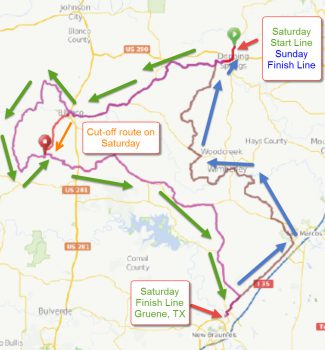
CTX_TDC_2016_2-Day_RouteEverybody is likely familiar with the American Diabetes Tour de Cure bicycle rides.  San Antonio held theirs last May and Austin will holding their 2-day event in September.   There are also rides held in Corpus Christi (April) and a new one being held in Laredo later this year that could use some ham help in the future.

If you have an Emergency Go-Kit, this is the perfect opportunity to dust it off and test it.  If you have a mast and portable beam antenna available, this would be a great time to use it.  Mobile radios will be required on high power.  A few locations might, maybe, be close enough to the repeaters to hit, or at least monitor using your HT, but don’t count on it.

The 2-day Austin Central Texas Tour de Cure ride this year, will start in Dripping Springs, loop out west around Blanco, TX, and then head south on Saturday over to Gruene, TX, just north of New Braunfels.  On Sunday, that 2-day ride will leave Gruene and wander north thru Wimberley, on it’s way back to Dripping Springs of course.

This ride is a bit different from those we have supported with ham radio communications in the past.   Their SAG vehicles are provided by the Austin based ABC Commercial Services company (formerly ABC Pest Control with that Ant Eater logo).   Rest stop supplies are coordinated by Austin Energy vehicles, with a few Penske trucks thrown in for good measure.   So that leaves mostly Rest Stops that need ham radio communications, plus a few trouble shooter hams that will be roaming the route in support of the MSET-TX motorcycle EMS group.

We’ve got some hams from the Hays / Caldwell ARC  on board, thanks to Mike Wilmore KF5ACHJeff Schmidt N5MNW is the overall ham coordinator, operating from the Austin / Dripping Springs main hub.  Lee Besing N5NTG is coordinating from the south end of the route.  Primary net control will be in Dripping Springs, with a backup net control in Gruene at the Saturday finish line.  Frequencies are being tested and will likely be using IRLP linked repeaters on 2 meters, but that may change depending upon the testing.

If you can help out either or both days, please contact Jeff Schmidt at n5mnw@arrl.net and Lee Besing at info@SanAntonioHams.org.  If you are a member of Hayes Caldwell ham club, please contact Mike Wilmore at mikewilmore@me.com.


Share
Aug 30

(Karnes County) The Otto Kaiser Memorial Hospital in Kenedy, Texas, has contacted us asking for help in joining the 21st century of ham radio communications.   🙂   I put them in touch with the ARES leaders for that district (Karnes County) and some others.  Ongoing discussion is starting up to cover a NDMS drill on the morning of September 20th.   The problem is that there are only about 10 hams licensed in that immediate area, with 2 of them (husband / wife) being registered hams and over the road truck drivers.

The hospital has a Kenwood dual band TM-D700 mobile radio that they are in the process of moving to a new location within the hospital.  They also want to establish HF Packet / Winlink capabilities.  Help with designing the antenna system and equipment will likely be needed.  I’m presuming the hospital is willing to budget for the equipment, but you know that presuming can be dangerous at times.

The latest word that I received (yesterday) was that the hospital would like someone to teach a class for some of their hospital employees and area volunteers to create a new batch of hams.    Of course, using HF would require a ham license of at least General class.

If you would like to help, please email me at info@sanantoniohams.org with the words “Karnes County” in the subject line.  I’ll forward your information to John Taylor KE5HAM (STXARES District 10 DEC)  in Victoria.

Share
Jun 16
W2IK LADDER LINE BACK PACK ANTENNA
     GREAT FOR CAMPING OR EMERGENCY COMMUNICATIONS
              
BOB HEJL – W2IK
EVER WISH YOU HAD A VERY SIMPLE, LIGHT WEIGHT HAM RADIO ANTENNA THAT COULD BE STUFFED IN YOUR BACKPACK AND DOES NOT NEED A TUNER? HERE IS A SIMPLE DESIGN THAT I BUILT MANY YEARS AGO AND FOUND IT TO BE VERY USEFUL WHILE CAMPING OR FOR EMERGENCY COMMUNICATIONS. IT’S GREAT IF YOU DON’T HAVE THE ABILITY TO TAKE ALONG MY “IK-STIC 2″ANTENNA (TO BUILD THAT ANTENNA, SEE ANOTHER POSTING ON THIS SITE.
WHEN YOU ARE CAMPING, YOU HAVE TO MAKE COMPROMISES. THE SAME IS TRUE ABOUT CAMPINGWITH HAM RADIO. USUALLY YOU’LL BE OPERATING ON 20 METERS IN THE DAY AND 40 METERS AT NIGHT. THAT BEING SAID, I DEVISED A VERY SIMPLE ANTENNA IN A SINGLE FORM THAT WILL COVER BOTH BANDS WITHOUT THE NEED FOR A TUNER.
TO BUILD THIS ANTENNA YOU WILL NEED
50 FEET OF 450 – 600 OHM LADDER LINE (NOT TWIN LEAD)
2 THREE INCH PIECES OF 1/2 INCH PVC TUBING
ONE CENTER CONNECTOR (DIPOLE TYPE-WIRE TO SO-239 CONNECTOR)
UNROLL THE COIL OF LADDER LINE AND CUT THE LADDER LINE IN HALF SO YOU HAVE TWO LENGTHS EXACTLY 25 FEET LONG.   EACH LENGTH BECOMES A SIDE OF YOUR DIPOLE SYSTEM. AT THE EVERY END OF EACH WIRE, STRIP OFF THE INSULATION EXPOSING ABOUT 4 INCHES OF BARE WIRE. ON ONE SIDE OF EACH LADDER LINE TWIST THE BARE WIRES TOGETHER AND SOLDER ONE END OF EACH LADDER LINE TO THE WIRES ON THE CENTER CONNECTOR.
 (SEE PICTURE BELOW)
AT THE OTHER END OF EACH OF THE LENGTHS OF LADDER LINE, TAKE ONE PIECE OF 1/2 INCH PVCTUBE AND SLIDE THE WIRES THROUGH 1/4 INCH HOLE DRILLED NEAR ONE END OF THE PVC TUBE. PULL THE PVC AROUND SO YOU CAN CONNECT THE WIRES TO EACH OTHER AND SOLDER THEM TOGETHER.
(SEE PHOTO OF THE ONE OF THE TWO END INSULATORS BELOW)
DRILL ANOTHER 1/4 INCH HOLE ON THE OTHER END OF THE PVC TUBE SO YOU CAN HANG THE DIPOLE SYSTEM UP USING NYLON CORD.
                           THE SPECIAL CUT
NOW JUST ONE MORE THING TO DO. IN ORDER TO MAKE THIS A 40 AND 20 METER ANTENNA, YOU NEED TO MEASURE 16.4 FEET FROM THE MIDDLE OF THE CENTER CONNECTOR AND ON ONE WIRE OF EACH SIDE OF THE LADDER LINE YOU WILL CLIP OUT A 1/4 INCH SECTION OF WIRE. IF POSSIBLE, CLIP THE SECTION OUT WHERE THERE IS A SEPARATING PIECE OF THE LADDER LINE WEBBING SO THE ANTENNA WILL BE PHYSICALLY MORE STABLE.
 THIS WILL LEAVE YOU WITH TWO ANTENNAS IN ONE SYSTEM. ONE ANTENNA’S TOTAL DIPOLE LENGTH IS 32.8 FEET (16.4 FEET ON EACH DIPOLE LEG) OR A 20 METER DIPOLE, AND THE OTHER IS THE 40 METER DIPOLE AS THE WIRE IN LADDER LINE YOU DIDN’T CLIP WILL NOW RUN THE ENTIRE LENGTH OF EACH SIDE, CONTINUE AROUND THE END INSULATORS AND CONTINUE IN A HAIRPIN  RUN AROUND TO THE OTHER (LOWER) SIDE OF THE LADDER LINE ON THAT SAME SIDE MAKING A LENGTH OF ABOUT 66.8 FEET TOTAL OR 33.4 FEET ON EACH LEG (LESS THAN THE MATH OF JUST ADDING AND SUBTRACTING BECAUSE YOU LOST LENGTH WHEN YOU SOLDERED THE WIRES THAT ARE IN THE END CONNECTORS) THIS IS FINE FOR A 40 METER DIPOLE.
 THERE IS JUST A LITTLE INTERACTION WITH THE TWO ANTENNAS SO CLOSE TOGETHER. IF YOU WISH TO BE REALLY FUSSY, YOU MAY WANT TO DO THE WIRE CLIP ACTION AND CHECK THE TUNING USING AN ANTENNA ANALYZER. IF THIS IS THE CASE, DO NOT CLIP OUT A 1/4 INCH PIECE YET, JUST CLIP THE WIRE, MEASURE THE SWR WITH THE ANTENNA HUNG AND MAKE ANY CORRECTIONS (DO THIS BYRESOLDERING THE CUT YOU MADE AND MAKE ANOTHER CUT DEPENDING UPON THE ANTENNA’SRESONANT FREQUENCY). ALTHOUGH THIS ANTENNA IS NOT AS EFFICIENT ON 40 METERS AS A DIPOLESTRUNG OUT INSTEAD OF FOLDED, I HAVE USED THIS ANTENNA ON MANY OUTINGS WITH GREATRESULTS AND IT IS MORE CONVIENT TO PUT UP OR STORE. YOU CAN EASILY COIL IT UP AND STORE INYOUR BACK PACK. IT CAN BE PUT UP AS A DIPOLE, SLOPER OR INVERTED “V”. MAKE SURE YOU HAVENON-CONDUCTING CORD TO HANG IT UP. AND BY THE WAY, SINCE THE 40 METER SECTION LOOPSAROUND, ALL YOU NEED IS 52 FEET BETWEEN TREES TO HANG THIS ANTENNA AS A DIPOLE!!!
LADDER LINE ANTENNA
COILED UP FOR STORING IN ABACK PACK SO IT CAN BE USEDWHILE HIKING OR CAMPING
ALL DESIGNS COPYRIGHTED
BY W2IK – BOB HEJL
MY NOT BE USED WITHOUT
AUTHOR CREDIT


Share
Jun 15
W2IK’s “IK-STIC 2”
DESIGNED BY BOB HEJL – W2IK
(PUBLISHED IN AUGUST 2004)
The “IK-STIC 2” is a vertical, all band, antenna that is over 25 feet tall yet weighs under 5 pounds !Using a tuner it can easily cover the amateur radio HF bands from 40 – 10 Meters.  No unsightly wires as the radiating wire is inside the telescoping mast!
TO CONSTRUCT THIS ANTENNA YOU NEED:
ONE SD-20 Telescoping mast (WorldRadio sells these)
ONE  6 foot section of 1 1/2 inch PVC Pipe
50 feet of 20 or 22 gauge STRANDED, INSULATED Wire
ONE SO-239 Barrel Connector with washers and Nuts
ONE male and female push on connectors (see photos)
TWO Large (6 inch) Hose clamps (see photos)
Electrical Tape, Epoxy, Duct tape and asst. hardware.

ANTENNA CONSTRUCTION


FITTING THE INTERNAL ANTENNA WIRE INSIDE THE TELESCOPING MAST:
Take the SD-20 telescoping mast and remove the bottom cap by unscrewing it.Looking in you will see the sections nestled in place. Remove the rubber plugfrom the next to thinnest section so now all the sections are “open”.  Carefullytake a 21 foot piece of 20 gauge, stranded, insulated wire and tie a very smallknot at the end. Take the knotted end and insert it into the smallest section ofthe telescoping mast and using a straight wire made from a coat hanger, shovethe stranded wire into the section as far as it can go. Then take a small amountof epoxy and glue the wire into place so it can’t be removed from the top section.SLOWLY telescope out the entire mast, making sure that the wire slides insideeasily. When the mast is fully extended you will have almost 20 feet of wireinside. Leave about 5 inches after the mast is fully extended and cut the wire.This will leave a 5 inch “play” to connect the wire at the bottom. NowCAREFULLY drill a small hole in the rubber base of the mast pointing outSIDEWAYS.  Epoxy a push on connector into the hole. Solder another 4 inchpiece of that same stranded wire onto the connector on the INSIDE. On thebottom cap of the mast, drill a hole that will allow you to half way insert, andtightly secure, that SO-239 barrel connector.  Carefully epoxy it on the inside ofthe cap so it won’t loosen. Next, solder the long wire that is in the mast onto theinner part of the SO-239 connector.  Solder the wire from the push on terminal tothe outer section of the SO-239 connector.  Take the cap and give it about 7 COUNTER CLOCK WISE turns so the two wires are twisted. This way, when youscrew the cap on, the wires will untwist in the mast.  Tighten the end cap, but donot glue it.
WINDING THE PVC COIL SECTION:
Next take 25 feet of that same stranded wire and start to wrap it around the 11/2″ PVC pipe at a point 14 inches from one end. (This becomes the top end.) MAKE SURE YOU LEAVE 8 inches of “free wire” before you start the coil wrap.Slowly wind the wire around the PVC pipe creating a coil, leaving a spacing of 11/2 – 2 inches from each turn. As you wind it down the pipe, you may wish tosecure it every so often with electrical tape. The winding does not have to be exact, but keep it as evenly spaced as you can. One foot before the bottom,create a tight wrap of the wire, leaving no gaps on the turns. At the end, tape thewire to the PVC pipe. When you are done, wrap the entire coil in electrical tape so the coil stays in place. On the top end, solder a mating end of a push onconnector so it can plug into the mast’s side connector.
Wrap several turns of Duct Tape to the very top of the PVC mast. This will serveto offset the taper in the telescoping mast when it gets mounted to the PVC pipe.  Using two adjustable hose clamps, carefully mount the very bottom of thetelescoping mast to the top one foot of the PVC pipe. DO NOT OVER TIGHTEN. It takes very little compression to keep the mast in place. When you have done this, you can extend the mast out it’s entire 20 foot length. To keep the entire antenna up-right, slip it over a 4 foot section of appropriate thin wall steel tubing that has been pounded in the ground about one foot. The lower coiled section of the antenna on the PVC pipe will then be slightly “ground coupled”. This helps with the antenna’s operation on 30 and 40 meters.  Plug in the lower coil (The PVC pipe) into the male  connector on the side of the telescoping mast. The SO-239 connector is where you screw in your coax cable to your radio. Make a few windings of whatever coax you are using at the connector point and tape them tightly together to prevent RF from returning on the coax shield. Connect the other end of the cable to your tuner and you are all set to go !!.
IMPORTANT: When you attach your coax to the antenna, make sure that the cable is dressed away and at as close to a right angle from the coil base for at least 5 feet and NOT down along it’s windings. Doing this will help prevent RF emitted from the coil from being radiated back on the coax shield and also will prevent “RF bites” at your radio point….ouch!  The pictures are merely for display and do not indicate the coax properly run.This step is very important in it’s proper operation. Keep the coax away from the coil assembly!
 To dis-assemble the antenna, just remove the coax, loosen the hose clamps and take down the mast after unplugging the PVC coil plug.  CAREFULLY retract the mast and the internal wire should slowly coil down into the masting. DO NOT FORCE THE SECTIONS. A few gentle jiggles and a twist or two will do the trick. After several uses it will be easier to retract the sections as the internal wire will have “memorized” how to coil up. You can even store the telescoping mast in the PVC pipe by making a small slot at the bottom of the PVC tube toaccommodate the connector that is on the side of the telescoping mast .   Theantenna is very simple, light and works well when tuned properly. My first contact was on 15 meters when I spoke to Siberia. I have used it on all the bands it covers and have also made an adapter so it mounts on the ball hitch of my truck. This is great when you are parked and can’t make a hole in the ground. (NOTE: If you wish to make an “IK-STIC 2” that covers 160-10 meters with a tuner, use a 7 FOOT PVC PIPE  instead of the 6 ft. PVC and coil  35 feet of wire around it using 1 inch spacing between wraps and two feet near the end increase the spacing until you run out of the wire and the end of the coil wrap is four – sixinches from the bottom of the PVC pipe. Any longer coil winding that this willmake it difficult to tune the antenna on 10 meters.) (Use the rest of the antennabuilding dimensions as outlined above.)
A SPECIAL NOTE: IF YOU ARE HAVING PROBLEMS WITH THIS ANTENNAIT CAN USUALLY BE TRACED TO THE FACT THAT WHEN YOU BUILT IT,YOUR INTERNAL WIRES TO THE CONNECTOR WERE EITHER NOT FULLY UNTWISTED OR YOU ALLOWED TOO MANY TURNS SO IT UNTWISTEDTHEN  TWISTED BACK. MAKE SURE YOU DO AN ACCURATE COUNT SOTHE TWO WIRES ARE NOT TWISTED  IF NOT THE WIRES WILL BECOUPLED AND THE ANTENNA WILL NOT WORK PROPERLY.
AN ADDITIONAL QUICKIE MODIFICATION:
Epoxy two 1 1/4 inch thin wall PVC sleeves to the lower section of the telescoping mast so they will prevent the telescoping mast from beingcrushed by “over exuberant” tightening of the two hose clamps that hold the telescoping section to the other (coil) section.
REMEMBER…. it’s called the “IK-STIC 2”  
Designed by Bob Hejl – W2IK
This antenna has been used at Field Day operations, SpecialEvents Stations, JOTA Events and County Activations with greatresults.


Share
Nov 4

Bexar County ARES has scheduled another Field Examination session for the ARRL Emergency Communications course to be held on December 1, at 5pm at the San Antonio Red Cross in classroom 3. The address is 3642 E Houston St. 78219.

So, if anyone would like to study up and take the test let us know.

Ref: http://www.arrl.org/emergency-communications-training

So far we have 1 ham interested. The requirements are: Identification (FCC license not required), there is the standard ARRL fee of $15, cash, and you must provide the dates of your completion of the FEMA course prerequisites, ICS-100 and 700.

73 Ray 210-845-2288

Share
Sep 14

The Fall SET is scheduled to coincide with MARS Field Day which is October 10th, 2015 from 8am to 12pm. The scenario this time around will involve shelter communications. MARS would very much like to see some ICS213 voice traffic so in conjunction with our regular fair of WINLINK ICS213 traffic, we’ll incorporate voice traffic as well. We’ll be sending out an SET Document beforehand.

73,
Frank N5SSH
STX ARES SEC

Share
Sep 11

Hill Country REACT Team 4804 will be holding their monthly  meeting on Tuesday,  22 September 2015 @ 1900 hrs.  The meeting is held at Picadillo’s  Restaurant in Bulverde.

Anyone interested in purchasing service and/or emergency communications is invited to attend.   Our team is very diverse and active with many benefit and community service activities in the region that require additional communication  via radio.

Looking forward to seeing some new faces.

Thank You,

Louis Upton – Hill Country REACT President


Share
May 24

The Skywarn Operators at the Austin-San Antonio NWO are in the process of updating our files and call-up list. Recently we have found the EC’s, Skywarn Coordinators and Net Controls have changed drastically in the various counties we serve.
It has also been found that several repeaters used in the past to contact and monitor Skywarn operations have changed or are no longer functioning.
If someone from each county could please e-mail me the contact information, frequencies and other pertinent information for ARES and Skywarn it would be greatly appreciated.
Also be advised that we have created a Facebook page and Twitter account to help get the word out. Feel free to like or follow to stay up to date with our operations.
Thank You, Louis – K5STX
e-mail to wx5exw at gmail dot com

Share

« Previous Entries Next Entries »